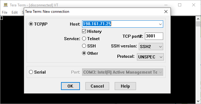
TERA TERM SERIAL PORT SERIAL
Those steps seem to be correct, but to connect the "UART" component in the PSoC to a PC,Ī way to convert UART serial to (probably) USB is required. Let me know whether the attached steps are correct or not?.* Service USB CDC when device is configured. * Enumeration is done, enable OUT endpoint to receive data * Initialize IN endpoints when device is configured. If (0u != USBUART_IsConfigurationChanged()) * Host can send double SET_INTERFACE request. USBUART_Start(USBFS_DEVICE, USBUART_5V_OPERATION) * Start USBFS operation with 5-V operation.
TERA TERM SERIAL PORT CODE
Please refer to the datasheet and the Cypress Provided Code Example " USBFS-UART" for more information. Note: Although the sample below seems to be working, I needed to select IMO 24MHz +/- 0.25% and enable USB
TERA TERM SERIAL PORT PC
In \CortexM3\ARM_GCC_541\Debug to let PC know what is this USB connection. The other from J2 (for USBUART connection)Īnd you need to place "USBUART_cdc.inf" file which Len-san attached at the discussion You need to connect 2 USB cables from CY8CKIT-050 to PC. When debugged from PSoC Creator, it worked just like the project above.

I confirmed that PSoC Creator is seeing "KitProg" Note only the USB cable from the KitProg is connected to PCĪnd from the Menu Debug > Select Debug Target. KitProg-SWDCLK White Jumper to CY8CKIT-050 P1_1 KitProg-SWDIO Green Jumper to CY8CKIT-050 P1_0 KitProg-RST Blue Jumper to CY8CKIT-050 RESET KitProg-GND Black Jumper to CY8CKIT-050 GND KitProg-VTARG Red Jumper to CY8CKIT-050 VIN KitProg-12 White Jumper to CY8CKIT-050 P0_1 KitProg-12 Green Jumper to CY8CKIT-050 P0_0 Then I connected these jumpers to CY8CKIT-050 The right side pins (J7) are for the debugger The nice part of KitProg is it has both "debugger" and "USB-Serial" on board. The picture is my two CY8CKIT-043s, one is still un-opened and the other is already separated to KitProg and the main board.Īfter I snipped the KitProg from the main board, I soldered pin-sockets so that using jumper wires will be easy. To get this tool, we need to get a Cypress's PROTOTYPE EVB, such as CY8CKIT-043. Then I tried to use KitProg, which is my favorite Note, I modified the main.c so that when I typed '1', 'M" is written Then when I debug the program, as I typed '0' and '1' I could see the LED on and off. (Sorry for these weird letters, they are called "Japanese Katakana") The other from the USB-Serial converter for UART input/output (This will be detected as a COM port from PC)ĬyGlobalIntEnable /* Enable global interrupts. One from CY8CKIT-050 J1 (for program and debug) Then I connected jumpers to CY8CKIT-050 as below

The following are the test I ran this morning.Īs I wrote in your other discussion before, I used a USB-Serial converter module I wonder if you are reading our responses.Īnyway, yesterday, I had a chance to visit my office after a few weeks of absence thanks for the COVID-19,


 0 kommentar(er)
